
Diy Guitar Effects Schematics
Effects, Schematics, Pedal, Tubes, Analog, Digital, MXR, Ibanez, BOSS, DOD, Tycobrahe, Tel-Ray, Morley, Kay, Peavey, Dallas Arbiter, Roger Mayer, Fender, Vox, Maxxon.

Should I Use A Guitar Amp Effects Loop? Andertons Blog
Block diagram ( of a typical pedal) The guitar signal enters the input section on the left. After being enabled by the Audio/Bypass switch, the signal gets modified in the Effects Section. There is sometimes a tone control to boost or cut the higher frequencies.

Coda Effects How to build your first DIY guitar pedal (step by step tutorial)
Guitar Effects Schematics & Projects PC boards for boosters buffers, fuzz and more! http://www.Muzique.com Guitar Effects Schematics EHX Doctor Q Dr. Quack - "fixed" version of the Doctor Q EHX Badstone Phase Shifter EHX Screaming Bird Treble Booster EHX Hot Tubes Distortion EHX LPB-1 Signal Booster EHX Mole Bass Booster EHX Muff Fuzz EHX Wah-Wah

How To Read Guitar Pedal Schematics
DIY Guitar Effects Pedals, Schematics, Stompboxes & Electronics New Kindle eBook! Guitar Effects Explained reveals the inside workings of stompboxes in easy to understand language. More Effects Books AMZ is a resource with information about diy guitar effects pedals, stompboxes, audio circuits and tips on how to build them.

Diy Guitar Effects Pedals Schematics
The components used in diy guitar pedal schematics can vary depending on the desired effect. Some common components include resistors, capacitors, diodes, transistors, and op-amps. These components work together to shape and manipulate the guitar signal, creating the desired effect.

Guitar Effects Schematics & Projects
Whether you're a complete beginner at building DIY guitar effects pedals or even a complete beginner with electronics in general, I'll help you get started on the path to building your first few pedals. Click here for my ultimate beginners guide to building DIY guitar effects pedals.

Guitar Effects Schematics & Projects
A transformer isolated signal splitter that enables hum-free connection of one guitar to more than one amp as well as having a direct output. The circuit is buffered to avoid signal loss. Phase 180 Plus. An update/extension of the Phase 90 with extra stages and controls for the experimenter. Phase 90/180 schematic.
Electro Harmonix FuzzWah Guitar Effect Circuit Scheme
The most common resistor value used when making DIY guitar effects pedals is 10K (10,000) Ohms. Throughout all 457 guitar pedal PCBs I analysed, I found that 1,546 10K Ohm resistors were used making this the most common value of resistor for building guitar stompboxes.

Guitar Effects Schematics & Projects
2. Using a Guitar Pedal Kit We cover several great options for DIY pedal kits above in this article. This is the perfect introduction to creating your effects, because it provides you with the room to be individual, while still sticking to a blueprint for guidance. Guitar pedal kits simplify the process dramatically.
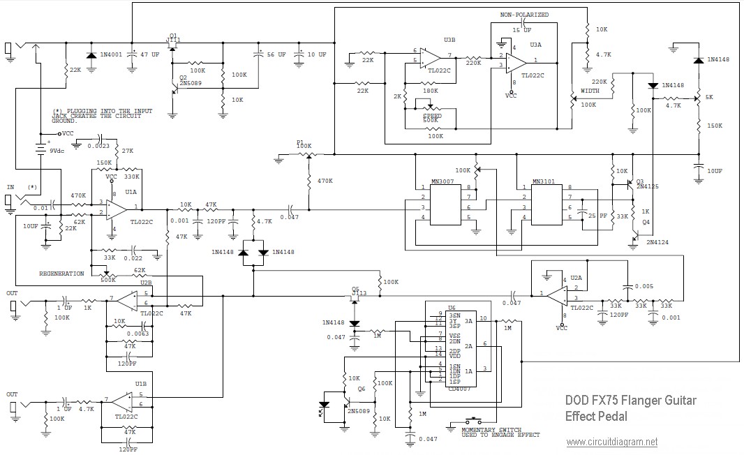
DOD FX75 Flanger Guitar Effect Pedal Circuit Scheme
Welcome to Schematics, wiring diagrams and detailed instructions for the best DIY Stompbox effects Projects on the internet. Ready-to-Solder PCBs or Complete Stompbox Kits are available for many of the projects. Contact us if you have any questions. Help Keep Our Site Free For Everyone!

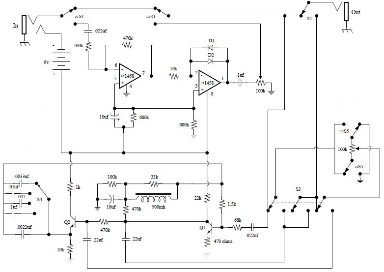
OctaverFuzz Guitar Effects Amplifier Circuit Design
Use a bipolar opamp for IC1, even the LM741 will sound good! If it is too fizzy sounding, increase C5 to 270pF or 560pF. For more bass response, increase C4 to 2.2uF or 4.7uF. Use red LEDs for D1 and D2 for more output. The tone control shown on the schematic has a big mid-range scoop.

Guitar Effects circuit
Guitar effects circuit diagrams provide a detailed overview of how each element of a custom effects pedal should be connected and configured. By using a schematic, guitarists can ensure that their electronics are properly wired and securely attached to their pedal's chassis. Furthermore, they can make sure that the current flowing through.

Diy Guitar Effects Pedals Schematics
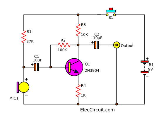
In the below image, a basic distortion pedal schematic using a transistor is shown. The transistor acts like a basic preamplifier. The 100K resistor is used as a collector resistor and the two capacitors are used for the audio input and audio output related purposes. The capacitors will block any DC and only pass the AC signal.

Guitar Effects Schematics & Projects
(June 29, 2020) Amplifiers & Headphone Amps Bass Boosters and Volume (Including Tone Boosters) Compressors Direct to Console/PA Distortion Filters, etc. Fuzz Tones Modulation, Echo, etc. Octave Effects Phase Shifters PowerSupplies Reverb Switchers & Routers Tone Controllers/Boosters Six Band Graphic EQ Project Tremolo Wah Wah Other

Guitar Effects Schematics & Projects
more than 20000 different guitar effects pedals from more than 3600 brands: vintage, modern, boutique, rare,.
Simple guitar fuzz effect circuit using IC741 Electronic projects circuits
Since 2011, Aion FX has been helping people get expensive tones for less. If you've never built a guitar pedal before, you'll find that our kits are a perfect place to start. And for those who are more experienced, we have DIY projects for over 200 different circuits, both vintage and modern. Building a pedal can be daunting.
